
ESHINE / Custom Architectural Applications
A material starting point for your next idea.
Bring a drawing, a spatial challenge or a new product concept. Develop the geometry, material and fabrication scope together.
THE APPLICATION
Move from an idea to a defined assembly.
Custom architectural work often begins where a standard product stops fitting the brief. A display may need to turn a corner, a counter may meet a curved wall, or an interior may call for a repeated family of shaped components. Solid surface offers several fabrication routes, but the useful question is which route suits the design, quantity and installation conditions.
ESHINE can discuss OEM and ODM development, cut-to-size material, CNC machining, suitable thermoforming and custom fabrication. The aim is to define a buildable assembly with a clear approval process. A concept drawing starts the conversation; coordinated dimensions, supports, material choices and delivery requirements make it possible to evaluate the actual production scope.
MATERIAL & DETAIL
Why choose solid surface?
One brief across several processes
A project may combine flat panels, machined openings, formed sections and joined edges. Reviewing those processes together helps identify dependencies before production. The selected formulation, color and finish influence the available route, so a custom design should remain open to informed construction decisions during development.
A coordinated family of components
A consistent material direction can connect separate architectural elements while allowing each one to have its own structure. Record the common finish reference and the details that differ. This is useful for a series of counters, displays or furniture elements distributed through an interior.
Approval through tangible details
A sample joint, edge section or prototype can answer questions that a rendering leaves open. Use the approval stage to review finish, geometry and assembly access. Document the agreed reference so that later drawing revisions and repeat orders do not silently change the intended result.
DESIGN POSSIBILITIES
Choose a route around the idea.
Shaped architectural components
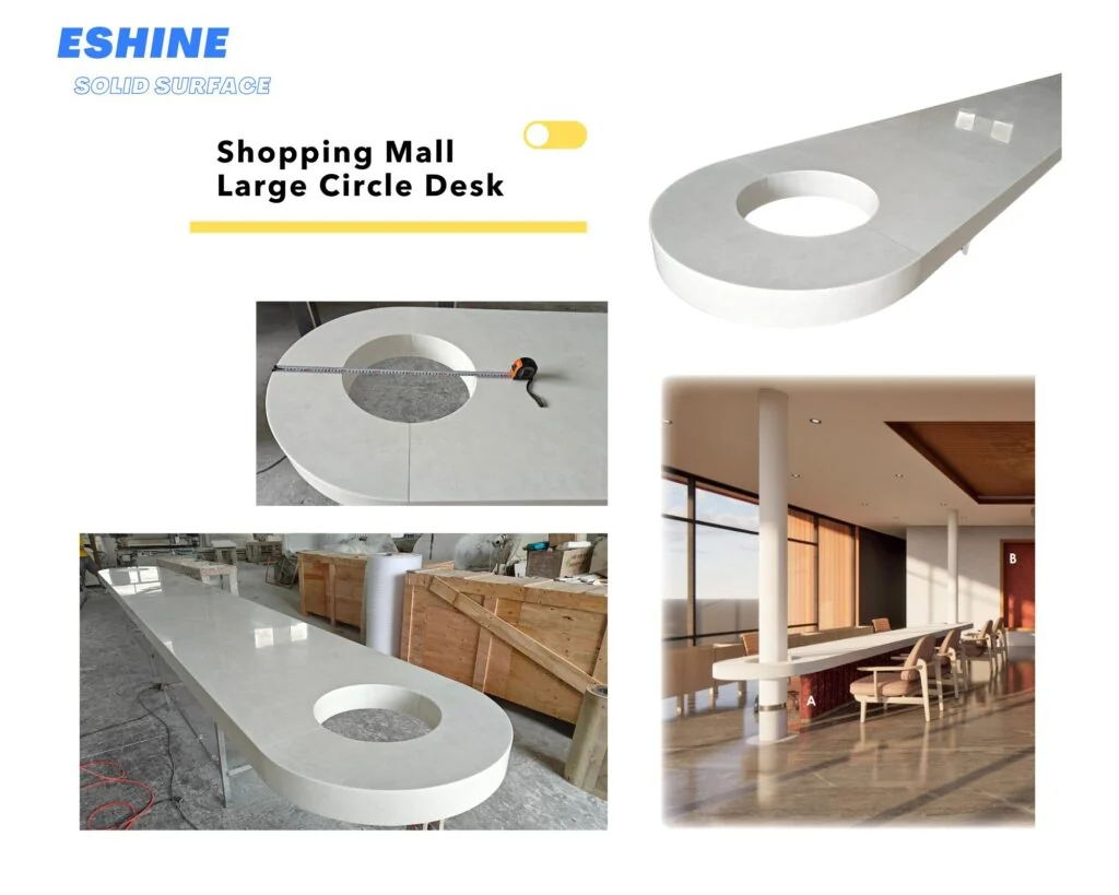
A shaped surround, reveal or integrated surface should be described in plan, elevation and section. Mark the visible faces and interfaces with adjacent trades. Where a form appears to be a solid volume, clarify whether it is intended as a fabricated enclosure and how the supporting construction works.
Curves, cut-outs and joined forms
CNC machining can prepare reviewed profiles and openings, while suitable thermoforming can be considered for curved elements. Neither process removes the need to check the chosen material. Complex forms may benefit from separate sections or a prototype to test assembly and the expected joint appearance.
Integrated interiors and branded fixtures
Custom displays and service elements can bring a brand's spatial language into a working fixture. Coordinate equipment, logo details, lighting and maintenance access from the start. A visually continuous surface should still allow the operator to reach the components that need inspection, cleaning or replacement.
MATERIALS & SPECIFICATIONS
Define the details.
Material direction
Use physical samples to review pure acrylic, modified acrylic, patterned or translucent directions against the actual design. Do not assume every formulation has the same forming behavior. Where illumination is proposed, review the material with the intended lighting assembly instead of relying on a screen image.
Formats and fabrication planning
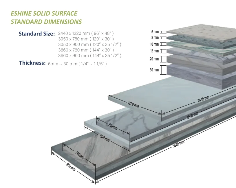
The sheet collection includes a 6mm to 30mm thickness range and listed formats including 3050×760mm, 3050×900mm, 3660×760mm, 3680×760mm and 2440×1220mm. Confirm the selected color, thickness and format combination for the order. Cutting yield, pattern direction and delivery sections influence the finished component layout.
Engineering and responsibilities
Provide intended use, loads, support details and relevant project requirements. The responsible designers should approve structure, fixings and regulated building interfaces. Define which technical development, fabrication, assembly and testing activities belong to each party so that an OEM or ODM brief has a clear scope.
APPLICATION GALLERY
A closer look.
PREPARE YOUR PROJECT
A useful first package does not need to be complicated.
Send the concept, approximate dimensions, intended environment, quantities and a color or finish direction. Add the destination, installation constraints and desired supply format. Identify decisions that are still open. ESHINE can then review the fabrication questions and agree what must be resolved in drawings, samples or a prototype before a production quotation and order approval are finalized.
View ProjectsRELATED PRODUCTS
Find your material starting point.
FREQUENTLY ASKED QUESTIONS
Before you specify.
Can I begin with a sketch instead of a finished drawing?
Yes. A sketch can explain the design intention and begin a feasibility discussion. Production still requires approved dimensions, material and construction details. Agree the design-development scope and the information needed for a reliable quotation before treating an initial concept as a manufacturing file.
Are all colors suitable for complex thermoformed shapes?
No universal forming claim should be assumed. Suitability depends on the formulation, selected color, thickness, geometry and process. Submit the proposed shape for review and agree any trial or prototype needed before approving a formed component.
Can a custom component become a repeat OEM product?
A reviewed prototype can become the reference for a repeat program once drawings, tolerances, finish criteria and packing are agreed. Record revisions and component identification clearly. Quantities, destination requirements and quality documentation should be confirmed as part of the commercial and production scope.
YOUR PROJECT / NEXT STEP
Request a Quote
Bring your concept, drawings or specification challenge. Define a practical material and fabrication route with ESHINE.